- TRANSDUCERS
- TRANSDUCERS
- BASIC COMPONENTS DK
- BASIC COMPONENTS DK
- MARKETPLACE
- MARKETPLACE
- DEVELOPMENT BOARDS & KITS
- DEVELOPMENT BOARDS & KITS
- CABLE ASSEMBLIES
- CABLE ASSEMBLIES
- RF AND WIRELESS
- RF AND WIRELESS
- BOXES ENCLOSURES RACKS
- BOXES ENCLOSURES RACKS
- AUDIO PRODUCTS
- AUDIO PRODUCTS
- FANS-BLOWERS-THERMAL MANAGEMENT
- FANS-BLOWERS-THERMAL MANAGEMENT
- WIRELESS MODULES
- WIRELESS MODULES
- TERMINALS
- TERMINALS
- Cables/Wires
- Cables/Wires
- SINGLE BOARD COMPUTER
- SINGLE BOARD COMPUTER
- BREAKOUT BOARDS
- BREAKOUT BOARDS
- LED
- LED
- TEST AND MEASUREMENT
- TEST AND MEASUREMENT
- DEVELOPMENT BOARDS AND IC's
- DEVELOPMENT BOARDS AND IC's
- EMBEDDED COMPUTERS
- EMBEDDED COMPUTERS
- OPTOELECTRONICS
- OPTOELECTRONICS
- INDUSTRAL AUTOMATION AND CONTROL
- INDUSTRAL AUTOMATION AND CONTROL
- COMPUTER EQUIPMENT
- COMPUTER EQUIPMENT
- CONNECTORS & INTERCONNECTS
- CONNECTORS & INTERCONNECTS
- MAKER/DIY EDUCATIONAL
- MAKER/DIY EDUCATIONAL
- TOOLS
- TOOLS
- MOTORS/ACTUATORS/SOLEENOIDS/DRIVERS
- MOTORS/ACTUATORS/SOLEENOIDS/DRIVERS
- FPGA HARDWARE
- FPGA HARDWARE
- ROBOTICS & AUTOMATION
- ROBOTICS & AUTOMATION
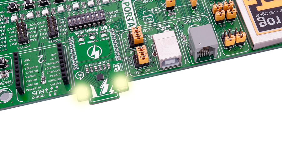
Note: Please be careful - do not look into the LEDs while they are on, it may be harmful to your eyesight.

CAT3224 features
The CAT3224 is a very high−current integrated flash LED driver which also supports the charging function for a dual−cell supercapacitor applications. Ideal for Li−ion battery−powered systems, it delivers up to 4A LED flash pulses, far beyond the peak current capability of the battery.
Dual−mode 1x/2x charge pump charges the stacked supercapacitor to a nominal voltage of 5.4 V, while an active balance control circuit ensures that both capacitor cell voltages remain matched.
The driver also features two matched current sources. External resistors provide the adjustment for the maximum flash mode current (up to 4 A) and the torch mode current (up to 400 mA). A built−in safety timer automatically terminates the flash pulse beyond a maximum duration of 300 ms.
The CAT3224 has a shutdown mode that is so low that ON Semiconductor can safely call it "zero" mode. In this mode, it typically uses only 1μA.
Information about the LED indicators
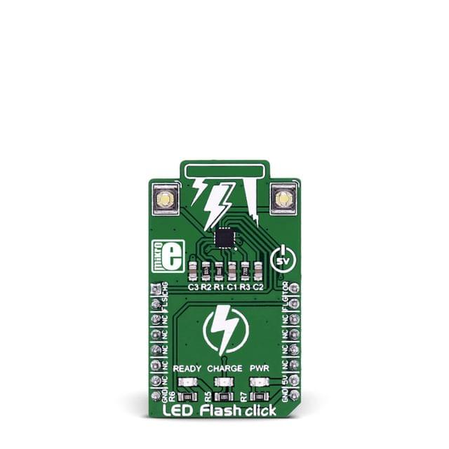
On the LED Flash click there are three different LED indicators, here is how they operate:
CHARGE — When this LED is on the driver is in charge mode.
READY — When this LED is on it indicates that the supercapacitor is fully charged.
PWR — Indicates if power is present.
Additional information about the pins
FLAG is an active−low open−drain output that notifies the microcontroller that the supercapacitor is fully charged by pulling the output low (pin 15 in the mikroBUS). When using FLAG, this pin should be connected to a positive rail via an external pull−up resistor.
TORCH is the torch mode enable pin. When high, the LED current sources are enabled in torch mode.
FLASH is the flash mode enable pin. When high, the LED current sources are enabled in flash mode. If FLASH is kept high for longer than 300 ms typical, the LED channels are automatically disabled.
LEDA, LEDB are connected internally to the current sources and must be connected to the LED anodes. Each output is independently current regulated. These pins enter a high−impedance ‘zero’ current state whenever the device is placed in shutdown mode or FLASH and TORCH are low.
Specifications
| Type | LED Segment |
| Applications | Applications that require a high power LED flash |
| On-board modules | CAT3224 flash LED driver |
| Key Benefits | Flash mode and Torch mode |
| Interface | GPIO |
| Input Voltage | 5V,5V |
| Click board size | M (42.9 x 25.4 mm) |
- Home
- LED Flash click
LED Flash click
SIZE GUIDE
- Shipping in 10-12 Working days
- http://cdn.storehippo.com/s/59c9e4669bd3e7c70c5f5e6c/ms.products/5aa3cc06c6738d86173b8ece/images/5aa3cc06c6738d86173b8ecf/5aa3c9889a66e885cc89db4f/5aa3c9889a66e885cc89db4f.jpg
Description of product
Note: Please be careful - do not look into the LEDs while they are on, it may be harmful to your eyesight.

CAT3224 features
The CAT3224 is a very high−current integrated flash LED driver which also supports the charging function for a dual−cell supercapacitor applications. Ideal for Li−ion battery−powered systems, it delivers up to 4A LED flash pulses, far beyond the peak current capability of the battery.
Dual−mode 1x/2x charge pump charges the stacked supercapacitor to a nominal voltage of 5.4 V, while an active balance control circuit ensures that both capacitor cell voltages remain matched.
The driver also features two matched current sources. External resistors provide the adjustment for the maximum flash mode current (up to 4 A) and the torch mode current (up to 400 mA). A built−in safety timer automatically terminates the flash pulse beyond a maximum duration of 300 ms.
The CAT3224 has a shutdown mode that is so low that ON Semiconductor can safely call it "zero" mode. In this mode, it typically uses only 1μA.
Information about the LED indicators
On the LED Flash click there are three different LED indicators, here is how they operate:
CHARGE — When this LED is on the driver is in charge mode.
READY — When this LED is on it indicates that the supercapacitor is fully charged.
PWR — Indicates if power is present.
Additional information about the pins
FLAG is an active−low open−drain output that notifies the microcontroller that the supercapacitor is fully charged by pulling the output low (pin 15 in the mikroBUS). When using FLAG, this pin should be connected to a positive rail via an external pull−up resistor.
TORCH is the torch mode enable pin. When high, the LED current sources are enabled in torch mode.
FLASH is the flash mode enable pin. When high, the LED current sources are enabled in flash mode. If FLASH is kept high for longer than 300 ms typical, the LED channels are automatically disabled.
LEDA, LEDB are connected internally to the current sources and must be connected to the LED anodes. Each output is independently current regulated. These pins enter a high−impedance ‘zero’ current state whenever the device is placed in shutdown mode or FLASH and TORCH are low.
Specifications
| Type | LED Segment |
| Applications | Applications that require a high power LED flash |
| On-board modules | CAT3224 flash LED driver |
| Key Benefits | Flash mode and Torch mode |
| Interface | GPIO |
| Input Voltage | 5V,5V |
| Click board size | M (42.9 x 25.4 mm) |
NEWSLETTER
Subscribe to get Email Updates!
Thanks for subscribe.
Your response has been recorded.
INFORMATION
ACCOUNT
ADDRESS
Tenet Technetronics# 2514/U, 7th 'A' Main Road, Opp. to BBMP Swimming Pool, Hampinagar, Vijayanagar 2nd Stage.
Bangalore
Karnataka - 560104
IN
Tenet Technetronics focuses on “Simplifying Technology for Life” and has been striving to deliver the same from the day of its inception since 2007. Founded by young set of graduates with guidance from ardent professionals and academicians the company focuses on delivering high quality products to its customers at the right cost considering the support and lifelong engagement with customers. “We don’t believe in a sell and forget model “and concentrate and building relationships with customers that accelerates, enhances as well as provides excellence in their next exciting project.


